|
|
|
 |
Building Tips |  |
|
|
|
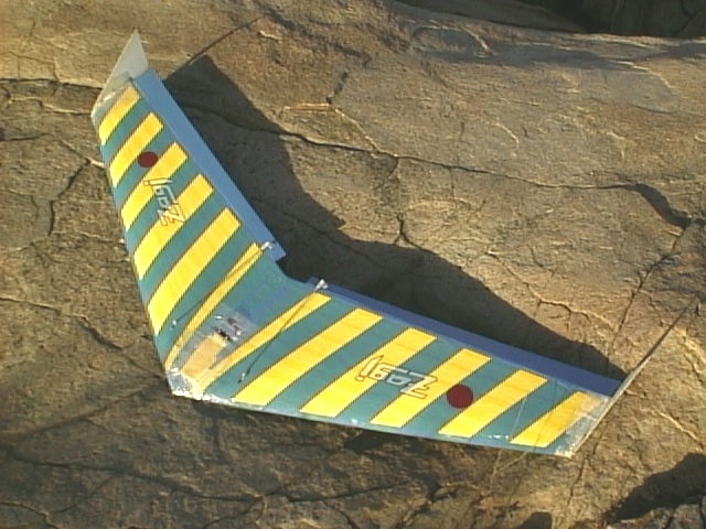 |
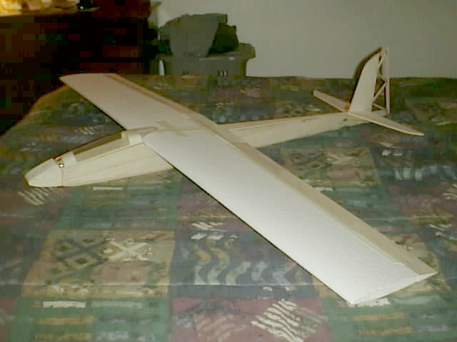
THIS WING IS ONE OF ZAGI'S COMBAT 3-C'S Built My the Editor: Sloper DON |
| Initial Set-up Control Throws for your FlyingWings. No matter which model wing you fly, be sure to take maximum advantage of its maneuverability by setting up the throws correctly. First and foremost, be sure your elevons move freely and your c/g is per specifications. A good starting point is for the ailerons to have maximum up and down movements. Some people dial in up to 120% for end point adjustment on their computer radios. Exponential rates on ailerons can be between minus 10% and minus 30%. This range allows for quick response without the controls being over sensitive. Elevator movement starting point can be about 75% of total movement. The elevator controls on most wings are usually pretty sensitive, so exponential rates can be anywhere form minus 25% to minus 60%. One way to check for proper elevator movement is to gain some altitude, put your plane into a shallow dive, and then pull up. If you do a nice loop, congratulations, you have the proper set-up. If your plane snaps out of the loop, decrease the throws. If it doesn't want to loop, increase the throws. Moving the c/g back a little can help you to loop, but may make recoveries from combat hits take a little longer. Radio Recommendations For an inexpensive first radio I recommend the Hitec Focus III Am Transmitter. It features 3 channel controls, V-tail and elevator mixing, and servo reversing. Even if you start with just elevator and rudder control gliders, you will probably want to graduate to flying wings. Until recently you would have to pay hundreds of dollars more to find a radio with elevon mixing necessary for wings. The third channel of the Hitec Focus III can be used for more advanced aircraft when the time arrives. At this price you do not get NiCads and a charger, but these can be purchased separately later. For the advanced flyer, I recommend the Hitec Flash 5X computer radio. It has 5 model memory, in flight timer,alarm and low battery warning. It has end point adjustments on all channels, servo reversing, exponential rates, mixing for ailerons/rudder, elevons, v-tail, flaperons, and proportional flaps on the throttle stick. All this for discounted! With proper programming,anyone can tune their plane for maximum performance and rail steady flying. |
|
|
|
|
| |
|
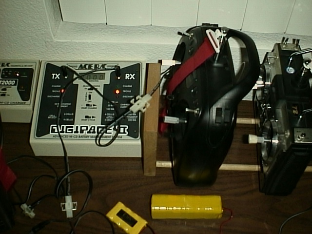 |
A Good Charger that Sloperdude Don uses is a ACE DigapaceII Cycler. |
| Charging Batteries Some issues of S & E Modeler magazine have gone into some detail regarding the batteries we use to power our airplane motors. This is a great magazine for people who fly sailplanes and electrics, and I highly recommend it. I have been flying electrics since around 1974 and would like to add some of my own observations regarding batteries. The standard connectors that come with most battery packs do not make a very good connection and usually can not handle current over 5 amps. Use Sermos, also known as Powerpole, Deans, Astroflight, or other high quality gold plated connectors for reliability. For the longest battery life and best reliability, choose a good charger. AstroFlight and Hitec both make high quality chargers that can charge up to 36 and 24 cells respectively using a 12 VDC power source such as an automobile battery. These chargers are the peak detection type, necessary for the proper charging of NiCad batteries. Peak detection chargers are necessary because during the first 70% of the charge cycle a NiCad battery absorbs almost all of the energy. After this point the battery cells start to generate gases and the temperatures rise. Excess heat, due to overcharging, is the greatest enemy to battery longevity. A peak detection charger will sense when the battery is at maximum charge and then stop charging before excess temperatures are reached. For long life do not recharge a battery while it is still hot from a recent discharge. Most peak detection chargers available at hobby suppliers only detect peak voltage, not heat. A test carried out by GTE Government Systems on NiCad batteries used in radios by the Navy showed that when these batteries were simply charged and used, 45% had to be replaced within one year. When the NiCads were exercised by bringing their voltage down to one volt per cell once a month,the annual replacement rate dropped to 15%. The typical sports flying we do several times a month is usually sufficient exercise for our NiCads even if the voltage doesn't drop down to one volt per cell. . Running down NiCads until the prop is barely turning after each flight is not a good idea. It can cause battery overheating, cell reversal, and armature warping of the motor. When cells were reconditioned by using a slow, deep discharge, bringing each cells voltage down to 0.6 volts, with careful control to prevent cell reversal, the annual replacement rate dropped to just 5%. Reconditioning is typically done with cells that have not been exercised for several months. I have "matched" cells purchased over five years ago, still going strong, that test to within .01 Volts per cell using these maintenance methods. Matched cells, especially when used in high current applications, are a good investment. Mismatched cells are sometimes found in new sport battery packs, as well as those that have aged. The reason for unevenly matched cells is poor quality control from the manufacturer and inadequate matching when assembling the batteries. If not too far off, cells in a new pack can adapt to each other with some initial slow charging at about 1 amp current. In an unmatched pack, weak cells hold less capacity and are discharged quicker than stronger cells. This imbalance can cause cell reversal in weak cells. Cell reversal is defined as when the stronger cells of the battery impose a voltage of reverse polarity across a weaker cell during deep discharge. In other words the plus side of the cell will now show a negative voltage and the negative side a plus voltage making the cell unusable. Also, the weak cells will reach a full charge first and go into heat generating overcharge while the stronger cells still accept a charge and remain cool. An easy way to detect a weak cell in a pack is to feel if one cell is warmer than the rest after charging. The weak cells are always at a disadvantage, making them weaker and contributing still further to their mismatched condition. There is a strong relationship between matched cells and the longevity of a battery, especially at high-load currents. When weak cells are detected it is best to replace them with cells that have a closer voltage to the other cells in the pack. I remove the weak cells and re-wire the pack temporarily so I can charge the remaining cells to capacity. I then charge the replacement cells to full capacity before soldering them into the pack. That way I can assure that all cells will have about the same state of charge before putting the pack into use. Anyone considering purchasing Nickel-Metal Hydride (NiMH) batteries should take into account that proper chargers for these type batteries are more complex than those for NiCads. Also NiMH cells tend to have more resistance than NiCad cells. They are recommended for use in radios and with motors that do not have a high current draw such as speed 400 or smaller motors. The 3000-mAh Sanyo NiMH cells seem to work o.k. up to about a 20 Amp discharge rate, but only have an actual capacity of around 2700 - 2800 mAh. At higher discharge rates they really heat up and the current flow decreases, severely effecting motor performance and eventually battery life. Manufacturers recommend that to achieve maximum capacity and service life, NiMH batteries be rapid charged rather than slow charged. Typically this should take around 2 hours for a fully discharged cell. Also, the amount of trickle charge needed to maintain full charge is critical. It MUST BE SET LOWER than for NiCds. A trickle charge that is acceptable for a NiCd will overcharge the NiMh battery and cause irreversible damage. A carger is necessary for the proper charging of NiMH cells. It measures the charge state of the battery, allows high current at the beginning of the charge, and avoids excessive temperature build-up towards the end of the charge. When temperature rise is minimized the battery can receive a fully saturated charge. The typical NiCad charger is not designed to provide such a fully saturated charge to the NiMh battery. Full-charge detection usually occurs with these chargers immediately after a given voltage peak is reached. Because of the absence of a topping charge, NiMH cells will not reach their maximum capacity. Another area to watch for carefully with NiMH cells is overcharging, even when they feel cool to the touch. The Tower Hobbies catalog shows three chargers that can charge 6 - 7 high capacity NiMH or NiCad cells. None mention step-differential charging, but their circuitry appears to supply this type of charging. The Intellipeak Pulse Chargers feature: Zero Delta V peak detection circuitry for NiMH cells. Computerized, microprocessor-controlled electronics and a host of other features. The MRC Super Brain 819 Delta Peak Charger constantly monitors pack status, switching from fast to trickle charge rates as needed. A unique DSP algorithm eliminates false peaks. The Novak Millennium DC Charger is one of the few chargers ideal for the 3000 mAh NiMH packs. Completely microprocessor controlled, it provides automatic analysis and conditioning of shorted packs; adjustable rates for linear and reverse pulse, and adjustable delta peak value. I am using the Dymond Modelsport Super Smart Delta Peak Battery Manager. It can use an automobile battery for input voltage and charges from 1 to 25 NiCad or NiMH cells or a 1 to 6 cell lead acid battery with a charging current from 0.1A to 5 A. It has fully automatic charge and discharge programs for NiCad batteries, 10 addressable memories to store charging and discharging parameters, incorrect polarity alarm and protection, and displays showing charge and discharge status time, charging or discharging current, input and output voltage, charge and discharge capacity, etc., etc., etc. Press one button and it automatically selects the best charge or discharge for your NiCads. Charging NiMH cells is another story. You have to program the charger yourself. Then you have to find what you programmed for the specific number and size of cells every time you charge them. The instructions claim easy programming,but not for me. I understand these chargers have been updated and are now easier to program. Check with Dymond. Kevin found the receiver battery in his ME 1111 low and wondered if it was O.K. to peak charge it so he could fly his plane in a short time. The usual rule is to charge receiver packs of up to about 600 mAh size at 10% of a battery's capacity for 14 to 16 hours. As an example, for longest life, a 600 mAh battery should be charged at a 60 mA rate, 250 mAh cells at 25 mA, etc. Any charge at a higher current rate will be detrimental to battery longevity. The standard plug-in battery charger that comes with your r/c radio has an output of around 50 mA. This is in order to properly charge the 500-mAh capacity receiver and radio batteries included in the system. Does this mean that Kevin won't able to fly his ME.1111 today? That depends on how much of a charge is in the receiver battery of his plane. Although some battery manufacturers will tell you not to fast charge receiver batteries under any circumstances, I have been able to get away with it on occasion. It is when my 4-cell receiver battery has over about 4.4 volts in it. I turn my charger down to a rate of 0.5 A and use the peak charge circuit. So far I haven experienced any battery failures using this method. If charging a battery for 14 to 16 hours is good, why not charge them for even longer periods of time at lower than the 10% rate? Battery manufacturers are strongly against doing this, warning that it can lead to serious battery failure. A NiCd battery loses about 10% of its capacity in the first 24 hours after being removed from the charger. Thereafter, the self-discharge rate is about 10% per month. Charging a battery at less than the 10% rate is like trying to fill your basin with the drain open. If we charge a NiCad battery at a rate of 10% of its capacity, shouldn't the charge time be 10 and not 14 - 16 hours? During the first 70% of the charge cycle a NiCad battery absorbs almost all of the energy, thereafter the energy absorption goes way down. The extra 4 to 6 hours used to slow charge receiver batteries gives them the time to absorb the remaining energy for a fully saturated charge. This long charge time and low charge rate are particularly important with radio and receiver batteries, where the cells may not be as well matched as in a motor battery. You can do a rough calculation of how long your receiver battery will fly your model in combat. Figure on a current rate of about 100 mA for each servo and about 25 mA for your receiver. If your wing uses a 225 mAh receiver battery you will have approximately 1 hour of flying time (100 + 100 + 25 = 225). These are numbers for full size servos in heavy-duty use. Less strenuous flying will draw less current resulting in longer flying times. If slow charging at a rate of 10% of their capacity is good for transmitter and receiver batteries, why not slow charge motor batteries? Motor batteries usually have higher capacities and higher charge rates than transmitter and receiver batteries. In fact manufacturers agree that generally it is better to fast charge these cells. This is because slow charging of these batteries can cause a build up of large crystals in the cells causing lower life and performance. This is also why these batteries can not be left on trickle charge indefinitely. Many battery manufacturers include instructions in new battery packs. You can your cells by using the minimum charging voltage recommended. There are a number of devices that you can take to the field for checking receiver batteries. The most common is the expanded scale voltmeter or simply ESV. These can put a typical system load (around 250 mA) on your pack. Prices start around . Don't relt do not put a load on the battery. Using a battery tester is good insurance against experiencing disaster at the slope with your favorite model. What is the "Memory Effect"? by: Sloerdud Don NiCad batteries, and to a lesser extent NiMH batteries, suffer from what's called the "memory effect". What this means is that if a battery is continually only partially discharged before re-charging, the battery "forgets" that it has the capacity to further discharge all the way down. To illustrate: If you, on a regular basis, fully charge your battery and then use only 50% of its capacity before the next recharge, eventually the battery will become unaware of its extra 50% capacity which has remained unused. Your battery will remain functional, but only at 50% of its original capacity. The way to avoid the dreaded "memory effect" is to fully cycle (fully charge and then fully discharge) your battery at least once every two to three weeks. Batteries can be discharged by unplugging the device's AC adaptor and letting the device run on the battery until it ceases to function. This will insure your battery remains healthy. Your New Battery Isn't Charging. What's the Deal Don? New batteries are shipped in a discharged condition and must be charged before use. I generally recommend an overnight charge (approximately twelve to Fourteen hours). Refer to your Transmitter and Receivers batteries user's manual for charging instructions. Rechargeable batteries should be cycled - fully charged and then fully discharged - 2 to 4 times initially to allow them to reach their full capacity. (Note: it is perfectly normal for a battery to become warm to the touch during charging and discharging). New batteries are hard for your charging device to charge; they have never been fully charged and are therefore "unformed". Sometimes your device's charger will stop charging a new battery before it is fully charged. If this happens, simply remove the battery from your device and then re-insert it. The charge cycle should begin again. This may happen several times during your first battery charge. Don't worry; it's perfectly normal. How Are Batteries Rated? (What Are Volts and Amps?) There are two ratings on every battery: volts and amp-hours (AH). The AH rating may also be given as milliamp-hours (mAH), which are one-thousandth of an amp-hour (for example, a 1AH battery is 1000mAH). The voltage of the new battery should always match the voltage of your original. Some of our batteries will have higher amp-hour ratings than the original battery found in your device. This is indicative of a longer run-time (higher capacity) and will not cause any incompatibilities. How Can I Maximize Battery Performance? The following practices will ensure maximum battery performance: Breaking In New Batteries - new batteries come in a discharged condition and must be fully charged before use. It is recommended that you fully charge and discharge your new battery two to four times to allow it to reach its maximum rated capacity. Preventing the Memory Effect - Keep your battery healthy by fully charging and then fully discharging it at least once every two to three weeks. Exceptions to the rule are Li-Ion batteries which do not suffer from the memory effect. Keep Your Batteries Clean - It's a good idea to clean dirty battery contacts with a cotton swab and alcohol. This helps maintain a good connection between the battery and your devise connection. Exercise Your Battery - Do not leave your battery dormant for long periods of time between flying. I recommend using the battery at least once every two to three weeks. If a battery has not been used for a long period of time, perform the new battery break in procedure described above. Battery Storage - If you don't plan on using the battery for a month or more, I recommend storing it in a clean, dry, cool place away from heat and metal objects. NiCad, NiMH and Li-Ion batteries will self-discharge during storage; remember to break them in before use. Sealed Lead Acid (SLA) batteries must be kept at full charge during storage. This is usually achieved by using special trickle chargers. If you do not have a trickle charger, do not attempt to store SLA batteries for more than three months. How Long Do Batteries Last (What is the Life Span of My New Battery)? The life of a rechargeable battery operating under normal conditions is generally between 500 to 800 charge-discharge cycles. This translates into one and a half to three years of battery life for the average user. As your rechargeable battery begins to die, you will notice a decline in the running time of the battery. When your two hour battery is only supplying you with an hour's worth of use, it's time for a new one. Should I Recycle My Old Battery? Nicad, NiMH and Li-Ion batteries should be recycled. Be environmentally conscious - do NOT throw these batteries in the trash. If you don't know where your local recycling facility is, call the Portable Rechargeable Battery Association at 1-800-822-8837. They will provide you with the address of the recycling center nearest to you. Make Your Own Battery What size cells should you choose? As mentioned last time in "The Flight Battery," flight of a carefully set up sailplane in the usual soaring mode demands very little from the flight battery. A 270-mAh battery should enable you to fly more than 1 hour if the battery is fully charged and the plane is set up properly. The smaller batteries can shave a little weight by using lead for balance instead of a larger battery. Regardless of choice of capacity, the flight battery never gets the high drain demand of the electric airplane. The elevated temperatures produced during over charge with a 10% capacity charger are just enough to notice if you hold the pack in your hand for a few seconds. Your choice of battery is similar to choosing a puppy as a pet, you will only know after it has been around for a while and you get to know it. The cheapest 500-mAh cells will give good service if you cycle them before placing them in service and keep a close check during use. I don t recommend using a new battery without recycling. What of choice of wiring harness for your new battery? Never use the old plug or wires because the old plug will be worn and dirty and the wires may have the "black wire disease." This disease it caused by the Ni-cad (nickel cadmium) electrolyte (concentrated potassium hydroxide paste) leaking from the vent or seals and wicking up the wiring harness, usually the positive. This corrodes the copper wire to a black copper oxide, weakening the wire, decreasing its current carrying capacity and making it almost impossible to "tin" with solder. I like to have a supply of #26 gauge, 19 strand, R/C wire and a few 8-pin Deans plugs and heat shrink to make new harnesses for battery packs. Common wire from Radio Shack will not work. The #26 gauge is large enough to carry the load of even a "big bird" radio and servos but because of the amount of movement the harness may receive, we need all the flex resistance possible. It is not funny to have a battery harness wire break during fight. Therefore, plan on having some sort of strain relief over the wires where the solder joint ends and the wire begins. This is the most likely place of failure. Any flexible plastic tubing that can be secured over the solder joint will do fine. I have used hot glue guns for strain relief over solder joints to switches, where the wires leave the battery wrapping and plugs, as a last resort. Heat shrink tubing works best and Radio Shack has a good assortment for this purpose. Try to use a black wire for the anode (negative) end of the battery and a colored wire, red if possible, for the cathode (positive). It may be easier to use an aileron extension, cutting off the plug not needed, for the harness. Note that Airtronics persists in coding their plugs with the positive (red) on the outside and the black wire in the center. Just the opposite of almost all other radios. Most builders cut the plug from the aileron servo and splice a long wire down to the receiver. It is a good idea to leave at least 1 inch of wire on the plug so that it can be used later for a flight battery. Figure 1 shows how to solder the tabs of the cells so that all are in series. Before soldering, I like to tape the cells together temporarily then use thick CA glue between each cell. (Note: Silicone works nicely). The proper size heat shrink tubing for the battery is difficult, so just cover it with some clear shipping tape when finished. (Note: Heat shrink for helicopter blades will sometimes do the trick). The soldered contact is fairly simple to make with a 25 watt pencil tip iron and rosin core (NOT acid core) solder about the diameter of the #26 gauge wine. Practice until you get a nice glossy smooth surface. A frosty or dull surface indicates that you have moved the wire while the solder is wet and caused the solder to crystallize forming a weak "cold solder joint." I like to tin (wet) both parts of an intended joint with solder, then, with one part in a vice or clamp, hold the other part very steady and touch the joint with the iron until I see the solder wick to the iron. A few seconds later, a nice joint is made. Finish by slipping the plastic strain relief over the joint securely. If you have no other way to cycle the battery, after full charge, turn on the radio and receiver and move two or more controls continually until you notice failure. This should occur in about 1 hour, just enough to watch a couple of 30-minute TV programs (Note: This is not the recommended procedure for cycling - There are many inexpensive cyclers on the market - use one.) Keep a check on the transmitter battery at the same time. If it fails first, you only know the capacity of the transmitter (approximately 200-mAh drain). Regular, continuous control movement will average about 250 mAh from the night battery, so use this figure with the time to calculate the capacity of this battery. Multiply time in hours by 250 mAh to obtain capacity of the battery pack. This constant movement is approximately 2 1/2 times the movement you would nominally use in flight. If you obtain an hour before failure using constant movement, then you should get at least 2 hours of flight from your new pack, depending on how you use your controls. |
|
 |
|
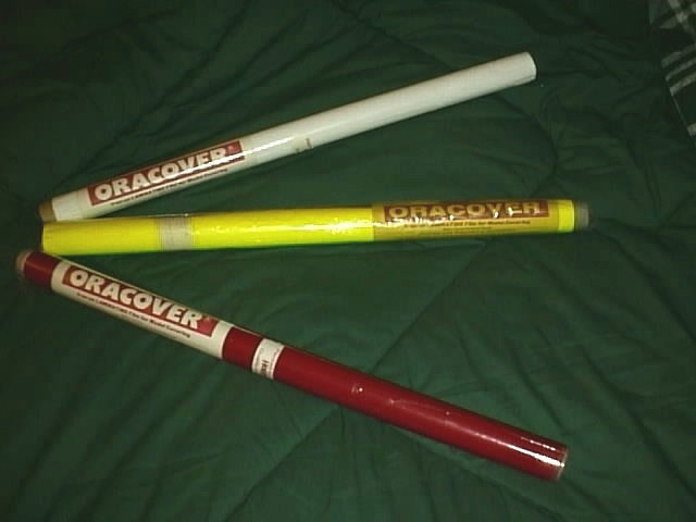
| ORACOVER MATERIAL FOR WINGS AND THINGS. I don't know how many of you Model Builders know about this new low temp covering but it work really well. I have been using it for about seven years and love it. You can Iron it on and if you make a mistake you can heat it up and re-apply it again. Oracover is a strong low-temp material that give you a smooth covering job and is easy to apply to any materail. I use it on all my Slope Planes and wings. NEW! Low-Temperature ORACOVER For years we assumed that the ready-built and ready-covered airplanes that we were getting from Germany, Czech Republic and other European countries were covered with regular Oracover. But when we compared the covering on these airplanes are particularly the lighter weight airplanes as to the Oracover that we stocked we discovered that the coverings were different. The planes were covered with a lighter-weight plastic film than the Oracover that we stocked. Light weight is important! The European manufacturers know this and have been using the lighter film on there models for a long time now. Old solid color Oracover weighed from 1.9 oz. to 3.2 oz. per square yard. The NEW Low-Temperature Oracover solid colors weigh from 1.8 oz. to 2.4 oz. per square yard. The NEW Low-Temperature Transparent Oracover weighs about 1.4 oz. per square yard. NEW! Low-Temperature Oracover comes in 26" wide, 78" long rolls. All rolls can be bought at www.hobby-Lobby.com How the NEW Low-temperature Oracover differs from the old Oracover: It's lighter. It shrinks much more and wrinkles can be more easily eliminated. It is applied at lower sealing iron temperatures. Because of its lower temperature application, it can be applied to wood-sheeted foam core structures without damaging the bond of the wood to the foam. How the NEW Low-temperature Oracover is similar to the old Oracover: Both are made of polyester instead of polypropylene plastic. Both have great strength and less rubbery characteristics than other plastic covering films. Both are to be applied onto sheeted surfaces with strokes from the center outward to get adhesion without trapping air bubbles. Order some from Hobby Lobby and try it out on your Slope Planes or Wings. and write me and let me know if you did or didn't like using this material. |
|
|
|
Tips on scratch built planes. Coming next months ... |
|
|
|